The overall concept of an OSPF virtual link is simple, a virtual connection from one area to join it to the backbone through another area, when no physical connection to the backbone area exists.
The configuration could be a little confusing, essentially you want to create a link between the router in the partitioned area (area without the physical connection) and the router within the transit area (connected to the backbone area). The command must be executed on both routers in order to bring up the virtual link.
Example topology below, R3 in Area 3 has no direct physical connection to the backbone area 0:
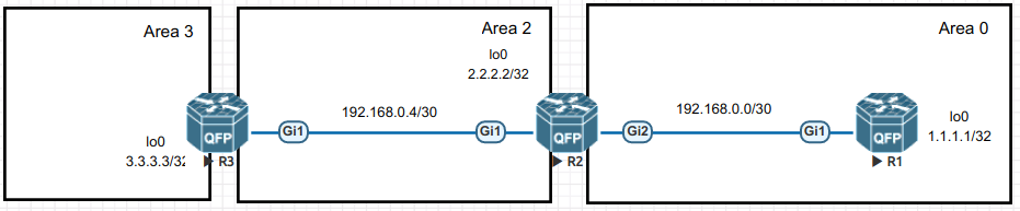
To create a virtual link, the command must be performed on both the ABR of the partitioned area (R3) that is connected to the transit area and also the ABR of the transit area (R2) which connects to the partitioned area 3 and also the backbone area.
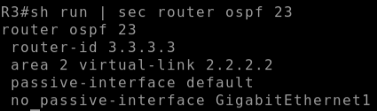
On R3 specify the target as the router ID of R2:
# area 2 virtual-link 2.2.2.2
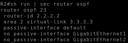
On R2 specify the target as the router ID of R3:
# area 2 virtual-link 3.3.3.3
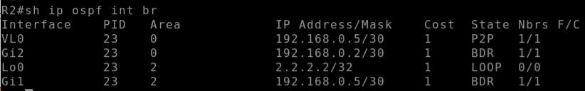
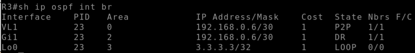
The virtual interface (virtual link) can now be seen on both R2 and R3:
R2 OSPF Interfaces:
R3 OSPF Interfaces:
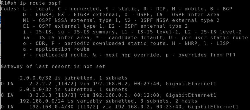
Once the ospf virtual link is in place, R1 (who was not receiving a route for 3.3.3.3 previously) now receives a route to loopback0 interface of R3 (3.3.3.3) and this route is seen as an Inter-area route:
In general this approach should not be considered a design tool, but instead used a tool to repair a network partition.